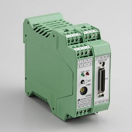
GYDC-05 controller enables digital output of 1μm resolution
and also analogue output of the position or the velocity (option).
With option, SSI output and the incremental output (A/B pulse)
are available.
And putting 2 pcs magnets on one probe and detecting each magnet
position or relative distance between 2 magnets are possible.
It has toggle switches on front face for zero/gain adjustment,
mounting with DIN rail.
With the captive software (GPM), zero and gain adjustment is
possible at user side.
・ CE marking
・ Noise cancellation
・ GPM setting
◆Auto-calibration
In combination with the probe (GYMR6, GYSE-R, GYKMR,
GYRHP-MR6) having auto calibration function, a difference in
the output when you change the probe is adjusted automatically.
( Created on Dec. 4.2025 )
| Position (digital)(24bit) | Parallel, Binary code (*1), Negative logic (*2) ( option :SSI or A/B incremental output ) |
|---|---|
| Resolution ( digital ) | Std. 0.01mm ( Min. 0.001mm ) (*3) 0.1mm (*4) |
| Position ( OUT1 ) ( analogue ) | 0〜10V ( Max.5mA, Min.2kΩ ) or 4〜20mA ( load :Max.500Ω) |
| Resolution ( analogue ) | 16bit ( 1/65536 ) (*3) ≦0.01%FS (*4) |
| Velocity ( OUT2 ) | Option ±10V or 4〜20mA |
| Alarm (*5) | Open collector 0.1A 30VDC |
| Power supply | +24VDC±2V ( ≦160mA ) |
| Sampling freq. (*6) | Std. 1kHz ( Total rod length : 1300mm ) |
| Temp. drift | ≦±10ppmFS/°C |
| Operating temp. | 0°C〜+65°C |
| Storage temp. | -20°C〜+75°C |
・The above mentioned accuracy applies to sensors with an effective stroke of 300mm or more.
・The specification of stroke less than 300mm is equal that of stroke 300mm.
(*1)can be changed to Gary code at user side
(*2)Tr On = output “0”
(*3)associated probe : GYMR6, GYSE-R, GYcRS, GYMR5, GYFRS,
GYKMR, GYRHP-MR6, EX-GYdT-RS
(*4)associated probe : GYMS, GYGS, GYPM, GYPE2K, GYPMR,
GYcRP, GYHTR, GYHR, EX-GYdS-RP, IGY4
(*5)cable disconnection and magnet drop
(*6)Sampling frequency is Max. 3.75kHz. It depends on the total rod length (model⑩),
and the consumption current increases.

① Digital output
1:Standard, parallel output
2100 :with A/B incremental(pulse freq. :1MHz)
2200 :with A/B incremental(pulse freq. :500kHz)
(standard for resolution D7 or D8)
2300 :with A/B incremental(pulse freq. :250kHz)
(standard for resolution D2-D5)
2400 :with A/B incremental(pulse freq. :125kHz)
2600 :with A/B incremental(pulse freq. :31kHz)
2700 :with A/B incremental(pulse freq.: 15kHz)
005A :with SSI output (26bit)
005S :with SSI output (26bit) : External sync.
・In case of A/B incremental, Max. magnet speed is limited with the selected resolution and pulse freq.
For standard setting, the speed is as below.
| Resolution(mm) | Pulse freq. | Max. magnet speed |
|---|---|---|
| 0.1 | 250kHz | (*)15m/sec |
| 0.05 | 250kHz | (*) 15m/sec |
| 0.01 | 250kHz | 8m/sec |
| 0.005 | 250kHz | 4m/sec |
| 0.002 | 500kHz | 3.2m/sec |
| 0.001 | 500kHz | 1.6m/sec |
② Resolution
D2 :0.1mm
D3 :0.05mm
D4 :0.01mm
D5 :0.005mm
D7 :0.002mm
D8 :0.001mm
「D4」is std. : GYSE-R, GYcRS, GYMR5, GYMR6, GYKMR, GYRHP-MR6, GYFRS, EX-GYdT-RS
「D2」only : GYGS, GYMS, GYPM, GYPMR, GYcRP, GYHR, GYHTR, EX-GYdS-RP, IGY4, GYPE2K
③ Direction of output
D :output data increase toward probe tip
R :output data decrease toward probe tip
④ Probe
MR6 :GYMR6
SR :GYSE-R
RS :GYcRS
RP :GYcRP
R5 :GYMR5
FS :GYFRS
HTR :GYHTR
HR24 :GYHR
MS :GYMS
GS :GYGS
PM :GYPM
P2 :GYP2K
PR :GYPMR
KMR :GYKMR
PMR6 :GYRHP-MR6
ETS :EX-GYdT-RS
ESP :EX-GYdS-RP
I4 :GY4
⑤ Effective stroke (mm)
⑥ Thread dead zone
□ :□ mm (option) (specified by customers)
⑦ Associated magnet or float
| magnet | float |
|---|---|
| MG0:No.Φ M0SM :No.ΦSPM M0LM :No.ΦLPM M2P:No.2P M2PN:No.2PN M3 :No.3 M11N :No.11N M11 :No.11 T144 :No.T14-M4 T142 :No.T14-M2 T163 :No.T16-M3 T162 :No.T16-M2 BA :No.2KYN-17-LG | F28S :Φ28 SS316L F30S :Φ30 SS316L F40S :Φ40 SS316(B) F42S :Φ42.5 SS316L F50S :Φ50 SS316L F54S :Φ54 SS304 F25N :RF-A10 plastic F28N :RF-A6 plastic |
⑧ Position output(OUT1)
AD :0-10V(When magnet moves toward tip, output increase)
AR :10-0V(When magnet moves toward tip, output decrease)
BD :4-20mA(When magnet moves toward tip, output increase)
BR :20-4mA(When magnet moves toward tip, output decrease)
CD□□ :bipolar output(-□V〜+□V)
(for example CD10 :-10V〜+10V)
CR□□ :bipolar output(+□V〜-□V)
(for example CR0 5 :+5V〜-5V)
V Z/F :option (specified voltage)
(for example V1/5 :1〜5V, V9.5/0.5 :9.5〜0.5V)
I Z/F :option (specified current)
(for example I5.2/20 :5.2〜20mA, I18/5 :18〜5mA)
【 Z=output at zero position, F=output at full position 】
⑨ Option : Analogue output(OUT2)
・N :without option (Std.)
・position output :select from ⑧
・velocity output(Note1)
VA[ ] :±10V
WB[ ] :4〜20mA
[ ]:max velocity (1.00-999mm/sec)
(ex.9R99: max velocity=9.99mm/sec)
(Note1)
VA :When magnet stops, output is 0V.
When moving toward probe tip, +10V.
WB :When magnet stops, output is 4mA.
When moving in any direction, 20mA
⑩ Option
2ME:2 magnets, each magnet position (analog output)(*)
2MR:2 magnets, relative distance between 2pcs(OUT1 only, analogue out put )
X2 :2kHz sampling (total rod length : Max. 700mm)
X3 :3kHz sampling (total rod length : Max. 500mm)
X4 :3.75kHz sampling (total rod length : Max. 400mm)
P :PNP (Parallel output)
HS :resin coating against humidity
(*) 2 magnets option
・ Min. proximity distance between magnets is 75mm.
(Min. proximity distance between magnets varies depending on the magnet type.)
・ When using other magnets, please consult our factory.
【Auto calibration function】
♦In combination with the probe (GYMR6, GYSE-R, GYKMR, GYRHP-MR6) having auto calibration function,
a difference in the output when you change the probe is adjusted automatically.
| Controller | Wiring | |||||
|---|---|---|---|---|---|---|