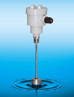
The GYTB-SA probe is a terminal block type level meter with a GYSE-A probe element built into the sensor.
The analog output has a high resolution of 16 bits.
It is also possible to use a multi-float system with two floats (output from each of the two floats) and to output the distance between two points.
The sensor element can be removed from the terminal block and replaced.
Zero/full scale point adjustment and output direction can be changed at the customer's site using optional equipment (with software) (Model: GPM).
Noise cancellation function
GPM
・ Voltage and current can be output at the same time (OUT1, OUT2)
・ Distance between 2 points (OUT1 only)
・ Position output of each float (float 1 = OUT1, float 2 = OUT2)
| Linearity | ±0.025% FS (Min.±50μm) Typ. |
|---|---|
| Resolution | 16bit (1/65536) |
| Output | Voltage output:0-10V (load :Min.2kΩ, output current : Max.5mA) Current output:4-20mA (load : Max.500Ω) |
| Temp. drift | ±20ppm FS/°C |
| Power supply | DC24V (±2V) 80mA |
| Sampling freq. | 100Hz (for level meter) |
| Operating temp. | -20 ~ +75°C |
| Storage temp. | -40 ~ +80°C |
| Viblation | 6G (or 40Hz 2mmPP) |
| Shock | 20G (2ms) |
| Protection grade | IP65 |

①Effective stroke[mm]: 50-7500mm
②Head dead zone
S : 50mm ( standard )
*: * mm ( option, specified by customers )
③Tip dead zone
S: 70mm:F28N
100mm:F40S、F42S、F50S、F54S
*: * mm ( option, specified by customers )
④Thread
B: R3/4( standard )
F: flange or ferrule (Please specify the type and size of flange or ferrule.)
⑤Rod diameter
Blank:Φ10( standard )
14 : Φ13.8
⑥Associated float
F40S:Φ40SS316(B)
F42S:Φ43SS316L
F50S:Φ50SS316L
F54S:Φ54SS304
F28N:RF-A6 NBR
⑦Position output(OUT1)
AD: 0-10[V]
AD:10-0[V]
BD: 4-20[mA]
BR: 20-4[mA]
CD□ or CR□: -□[V]-+□[V](bipolar
⑧Option : analogue output(OUT2)
N: without option (standard)
・If you need option, select the symbol form ⑦.
⑨High temperature option (rod parts only)
Blank: 80°C(Std.)
H0 :100°C
| Dimension | Terminal box | |||||
|---|---|---|---|---|---|---|
 |  | |||||
-Material: Probe head: Aluminum alloy (AC2A), Probe rod: SUS316
-Power supply is connected to [24V] and [0V] on the lower terminal block.
-Outputs are connected to [OUT1] and [COM1] on the upper terminal block.
-Alarm output is output to [ALM] and [COM3] on the upper terminal block.
-Option output is output to [OUT2] and [COM2] on the lower terminal block.
-COM1, COM2 and COM3 are connected internally.
-The shielded braid wire is connected to the screw on the board (one of five places), and the other end is grounded.
(If grounding has an effect on noise, leave it unconnected.)
*Cable is not included.
Use a batch shielded wire of 5 or more cores (cable outer diameter: Φ5 to Φ8.8, wire size: 0.2 sq. or more).
The standard cable length is 10 m for voltage output and 100 m for current output