
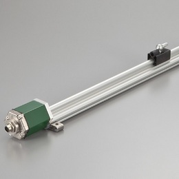
This is the linear profile version of GYSE-A.
It is a high performance analog output probe, and has the high
resolution of 16bit.
It has also velocity output.
Using two pcs of magnet on the probe as another option, detecting
each magnet position or relative distance between the two is possible.
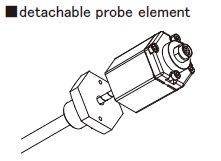
The inside probe element can be detached from the outer housing,
and with the captive software (GPM), zero and gain adjustment is
possible at user side.
・ CE marking
・ Noise cancellation
・ GPM setting
( Created on Nov. 21. 2025 )
| Non-linearity | ≦±0.025%FS Typ. |
|---|---|
| Resolution | 16bit (1/65536) |
| Repeatability | ≦±0.001%FS (Min. ±3μm) |
| Temp. drift | ≦±20ppmFS /°C |
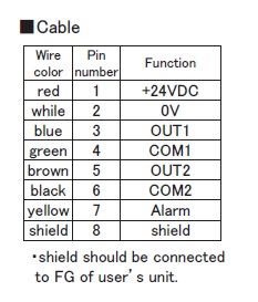
| Position (Std.) | 0〜10V or 10〜0V ( output current : Max. 5mA, load: Min. 2kΩ ) or 4〜20mA ( load : Max.500Ω ) |
| Velocity (Option) | ±10V ( output current : Max. 5mA, load: Min. 2kΩ ) or 4〜20mA ( load : Max.500Ω ) |
| Alarm | Open drain 50V 0.1A ( for magnet missing ) |
| Power supply | +24(±2)VDC (80mA) (*1) |
| Sampling freq. (*2) | Std. 1kHz ( Total body length : 1300mm ) |
| Operating temp. | -20°C〜+75°C |
| Storage temp. | -40°C〜+75°C |
| Vibration | 15G ( 20〜100Hz ) |
| Shock | 100G ( 2msec ) |
| IP grade | IP65 |
・The above mentioned accuracy applies to sensors with an effective stroke of 300mm or more.
・The specification of stroke less than 300mm is equal that of stroke 300mm.
(*1) The consumption current is 100mA in case of adding OUT2 option (Model ⑦).
(*2) Sampling freq. is available to Max. 3.75kHz by option. It depends on the total body length (shows in Model ⑧),
and the consumption current increases.
・Fixing clamps are supplied. (One clamp is added every 500mm.)
stroke < 600mm:2 pcs
600-1000mm:3 pcs
1001-1500mm:4 pcs
1501-2000mm:5 pcs

① Effective stroke
15〜7500mm
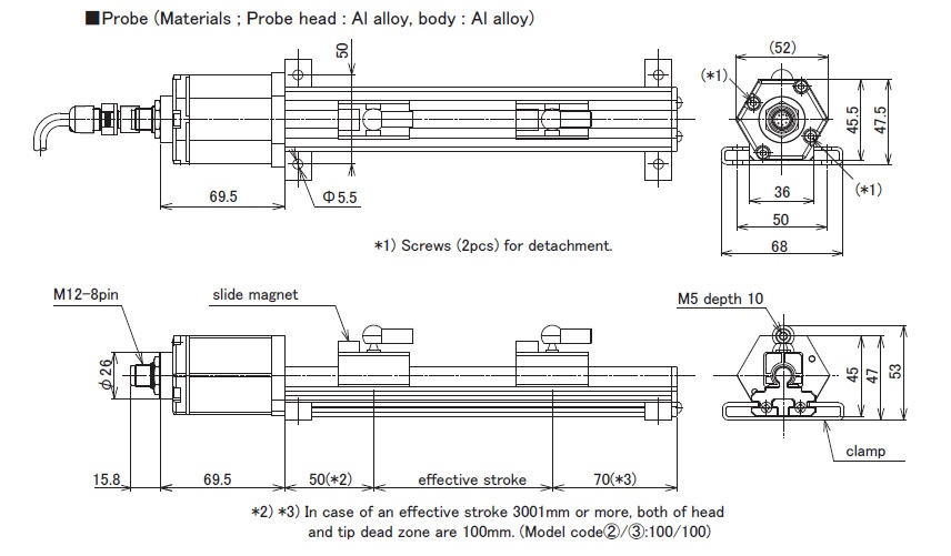
② Head dead zone
50 :50mm (Std.)
□ :□mm ( option ) ( specified by customers )
・Possible Min. length depends on the selected magnet or float.
③ Tip dead zone
70 :70mm(Std.)
□ :□mm (option) (specified by customers)
・Possible Min. length depends on the selected magnet or float.
④ Associated magnet
PFU :PFU slide magnet
FE :No.5N-UK
BP :No.5PFT-LG
M11N :No.11N
M11S :No.11S
・Please consult if you select a magnet of other than above.
・This Model code means only specifying associated magnet.
・When you need a magnet, please order separately.
⑤ Cable connection
8P:connector
△G□F :pigtail / cable end : free
△G□A :pigtail / cable end : with connector for relay
(□ :cable length(m)、Max.10m)(*)
(△ :cable type
S:standard, H:high temp. cable, R:robot cable, UL : cUL cable)
CN:existing connector (Please refer to P.109 of option.)
(*) In case of using extension cable
Voltage output : sensor cable (m) + extension cable (m) ≦ 10m
Current output : sensor cable (m) + extension cable (m) ≦ 100m
・Please confirm extension cable on page 120-122.
・Ordering loose mating connector individually.
⑥ Position output(OUT1)
AD :0〜10V(When magnet moves toward tip, output increase)
AR :10〜0V(When magnet moves toward tip, output decrease)
BD :4〜20mA(When magnet moves toward tip, output increase)
BR :20〜4mA(When magnet moves toward tip, output decrease)
CD□□ :bipolar output(-□V〜+□V)
(for example CD10:-10V〜+10V)
CR□□ :bipolar output(+□V〜-□V)
(for example CR05:+5V〜-5V)
V Z/F :option (specified voltage)
(for example V1/5:1〜5V, V9.5/0.5:9.5〜0.5V)
I Z/F :option (specified current)
(for example I5.2/20:5.2〜20mA, I18/5:18〜5mA)
【 Z=output at zero position, F=output at full position 】
⑦ Option : Analogue output(OUT2)
・N :without option (Std.)
・Position output :select from ⑥
・Velocity output(Note1)
VA[ ]:±10V
WB[ ]:4〜20mA
[ ]:max. velocity(1.00〜999 mm/s)
(Note1)
VA : When magnet stops, output is 0V. When moving toward probe tip, +10V.
WB : When magnet stops, output is 4mA. When moving in any direction, 20mA.
⑧ Option
blank :without option
X2 :2kHz sampling (total body length : Max. 700mm)
X3 :3kHz sampling (total body length : Max. 500mm)
X4 :3.75kHz sampling (total body length : Max. 400mm)
⑨ Clamp
F50 :with fixing clamps
N :without fixing clamps
⑩ Two Magnets Option
A :one magnet (STD)
A2MR :two magnets (relative distance between the two)(*)
A2ME :wo magnets (each magnet position)(*)
(Please consult factory)
(*) 2 magnets option
・ Min. proximity distance between magnets is 75mm.
(Min. proximity distance between magnets varies depending
on the magnet type.)
・ When using other magnets, please consult our factory.
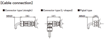
In case of connector type, connector dimensions are different from the existing product.
Please refer to page 115 for the existing one (LEMO).
・Connector (M12-8pin) : Amphenol
(materials: glass fiber reinforced plastic)
| Probe | Cable | Detachable probe element | ||||
|---|---|---|---|---|---|---|
 |  |  | ||||