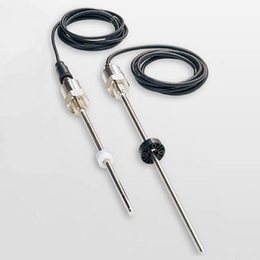
The design of GYMS makes the sensor head compact.
Its linearity is ≦±0.025%FS and its protection is IP67.
◆Associated controller
・Analogue output:GYHC
・Digital output:GYDC-S1, GYDC-05
・IRDS-GY : When using the IRDM, you can connect with
CC-Link, CC-Link IE Field, PROFIBUS, EtherNet/IP, and EtherCAT.
( Created on Feb. 3. 2023 )
| Non-linearity | ≦±0.025%FS Typ. |
|---|---|
| Resolution | ( analogue ) ≦0.01%FS ( digital ) 0.1mm |
| Repeatability | ≦±0.01%FS |
| Temp. drift | ≦±40ppmFS/°C |
| Max. Pressure | 35MPa ( probe rod ) |
| Operating temp. | -20°C〜+80°C |
| Storage temp. | -40°C〜+80°C |
| Vibration | 6G ( or 40Hz 2mmPP ) |
| Shock | 50G ( 2msec ) |
| IP grade | IP67 |
・The above mentioned accuracy applies to sensors with an effective stroke of 300mm or more.
・The specification of stroke less than 300mm is equal that of stroke 300mm.

① Effective stroke
15〜3000mm
② Head dead zone
50: 50mm (Std.)
□: □mm ( option ) ( specified by customers )
・Possible Min. length depends on the selected magnet or float.
③ Tip dead zone
□: 70mm/ 90mm/ 100mm (Std.)
| □ | tip DZ | magnet | float |
|---|---|---|---|
| 70 | 70mm | M2PN, M0SM, M0LM, M3, M11N, BA | F25N, F28N |
| 90 | 90mm | F28S, F30S | |
| 100 | 100mm | T144, T163 | F40S ,F42S, F50S, F54S |
④ Thread / Rod diameter
J8 : M20xP1.0, rod Φ8(Std.)
L8 : M16xP2.0, rod Φ8
E8 : M20xP1.5, rod Φ8
N : M18xP1.5, rod Φ10
U : 3/4-16UNF-3A, rod Φ10
K6 : M16xP1.5, rod Φ6
・In case of an effective stroke 1001mm or more, the rod Φ10 should be used.
| magnet | float |
|---|---|
| M2PN :No.2PN (Std.) M0SM :No.ΦSPM M0LM :No.ΦLPM M3 :No.3 M11N :No.11N T144 :No.T14-M4 T163 :No.T16-M3 BA : No.2KYN-17-LG | F28S:Φ28 SS316L F30S :Φ30 SS316L F40S :Φ40 SS316(B) F42S :Φ43 SS316L F50S :Φ50 SS316L F54S :Φ54 SS304 F25N :RF-A10 plastic F28N :RF-A6 plastic |
・Selecting magnet from page 116〜118(GG).
・Please consult our factory in case of requesting special magnet or float.
・This model code means only specifying associated magnet or float.
・Ordering magnet or float individually.
・In case of an effective stroke 2001mm or more, "No.2KYN-17-LG"
magnet (page 116) would be recommended.
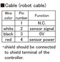
⑥ Cable connection
G□F: pigtail / cable end : free
G□A: pigtail / cable end : with connector for relay
(□: cable length(m)、Max.10m) (*)
CN: connector
(*) In case of using extension cable
sensor cable (m) + extension cable (m) ≦ 100m
・Please confirm extension cable on page 120〜122.
・Ordering loose mating connector individually.
⑦ Output
00 :depends on external controller (total rod length : ≦1400mm)
24 :depends on external controller (total rod length : ≧1401mm)
| Probe | Connector | Cable | ||||
|---|---|---|---|---|---|---|
 |  | |||||