| Non-linearity | ≦±0.05%FS Typ. |
|---|---|
| Resolution | ( Analogue ) ≦0.03%FS ( Digital ) 0.1mm |
| Repeatability | ≦±0.03%FS |
| Temp. drift | ≦±0.01%FS / °C |
| Max. Pressure | 18MPa ( probe rod, static for 10 min. ) |
| Operating temp. | -20°C〜+80°C |
| Storage temp. | -40°C〜+80°C |
| Vibration | 3G ( or 40Hz 1mmPP ) |
| Shock | 20G ( 2msec ) |
| IP grade | IP64 |
・The above mentioned accuracy applies to sensors with an effective stroke of 100mm or more.
・The specification of stroke less than 100mm is equal that of stroke 100mm.

① Effective stroke
15〜250mm
② Head dead zone
35 : 35mm ( No.Φ magnet )
28 : 28mm ( Ti float )
□ :□mm ( option ) ( specified by customers )
・Possible Min. length depends on the selected magnet or float.
③ Tip dead zone
30 : 30mm ( No.Φ magnet )
42 : 42mm ( Ti float )
□ :□mm ( option ) ( specified by customers )
・Possible Min. length depends on the selected magnet or float.
④ Thread / Rod diameter
Y4 :M18xP1.0, rod Φ4 (Std.)
| magnet | float |
|---|---|
| MG0 :No.Φ (Std.) | FL21 :Ti |
・This model code means only specifying associated magnet or float.
・Ordering magnet or float individually.
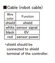
⑥ Cable connection
G□F :pigtail / cable end : free
G□A :pigtail / cable end : with connector for relay
( □:cable length (m))
・Cable length is Max. 5m and the specified length can not be changed
at user's side. Not possible to make it short or add extend cable.
It is possible to cut cable and attach terminal stand or relay connector
without changing total cable length.
・Please confirm extension cable on page 120〜122.
⑦ Output
00 :depends on external controller
| Probe | Cable | Ti float | ||||
|---|---|---|---|---|---|---|
 |  |  | ||||
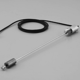
・ The M5 screw installed in the rod tip can be used as float stopper or to fix the sensor.
・ When the sensor rod part is to be sealed, O ring should be used, refer to detail A drawing.