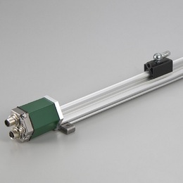
This is the linear profile version of GYSE-P.
It is PROFIBUS interface type.
Setting parameters (resolution, output direction) through PROFIBUS is possible.
GSD file is available on SANTEST web site.
Detecting up to 32 pcs of magnets on one probe is possible (Min.
proximity distance between 2 magnets is 75mm).
When you use a PROFIBUS master simulator of separate sale, it's
possible to confirm the data and to set up a PROFIBUS slave from
a PC without PROFIBUS master (usually, PLC).
・ CE marking
・ Noise cancellation
( Created on Feb. 7. 2023 )
| Non-linearity | ≦±0.025%FS Typ. |
|---|---|
| Resolution | Min. 1μm ( set by Profibus Configurator ) |
| Repeatability | ≦±0.001%FS ( Min. ±3μm ) |
| Temp. drift | ≦±15ppmFS / °C |
| Output | Profibus DPV0 |
| Power supply | +24(±2)VDC (70mA) |
| Sampling freq. | Stroke 〜800mm : 2000Hz 〜2200mm : 1000Hz 〜5000mm : 500Hz 5001mm〜 : 250Hz |
| Operating temp. | -20°C〜+75°C |
| Storage temp. | -40°C〜+75°C |
| Vibration | 15G ( 20〜100Hz ) |
| Shock | 100G ( 2msec ) |
| IP grade | IP65 |
・The above mentioned accuracy applies to sensors with an effective stroke of 300mm or more.
・The specification of stroke less than 300mm is equal that of stroke 300mm.
(*) In case of multi magnets on one probe, sampling frequency is not standard value.
・Fixing clamps are supplied. ( One clamp is added every 500mm )
stroke < 600mm:2 pcs
600-1000mm:3 pcs
1001-1500mm:4 pcs
1501-2000mm:5 pcs

① Effective stroke
15〜7500mm
② Head dead zone
50 :50mm (Std.)
□ :□mm (option)(specified by customers)
・Possible Min. length depends on the selected magnet.
③ Tip dead zone
70 :70mm (Std.)
□ :□mm (option)(specified by customers)
・Possible Min. length depends on the selected magnet.
④ Associated magnet
PFU :PFU slide magnet
FE :No.5N-UK
BP :No.5PFT-LG
M11N : No.11N
M11S : No.11S
・Please consult our factory in case of requesting special magnet.
・This model code means only specifying associated magnet.
・Ordering magnet individually.
⑤ Cable connection
CN :connector
⑥ Option
blank :without option
L :linearization option(≦0.006%FS Typ.)
2M : temperature compensation (≦±7ppmFS /°C)
2ML : temperature compensation + Linearization
⑦ Option
F50 :with fixing clamps
N :without fixing clamps
・ Standard pcs (depend on stroke) of the clamp are applied.
Possible to order extra pcs individually.
・ Please refer to page 118 for clamp drawings.
| Probe | Connector | Wiring | ||||
|---|---|---|---|---|---|---|
 |  | |||||
■ Connector and Cable Models
・Power supply connector :CN-SEP-M8-□
・Profibus connector (IN, male) :CN-SEP-M12M-○□-△
・Profibus connector (OUT, female) :CN-SEP-M12F-○□
・Terminal :CN-SEP-TR
○ :cable length(m),
S :standard
R :robot cable
□ :cable length(m)
In case of “0”, it means loose connector only
△ :blank :loose connector (IN, male)
M12F :with connector (OUT, female) at the other end
(Need to specify cable length)